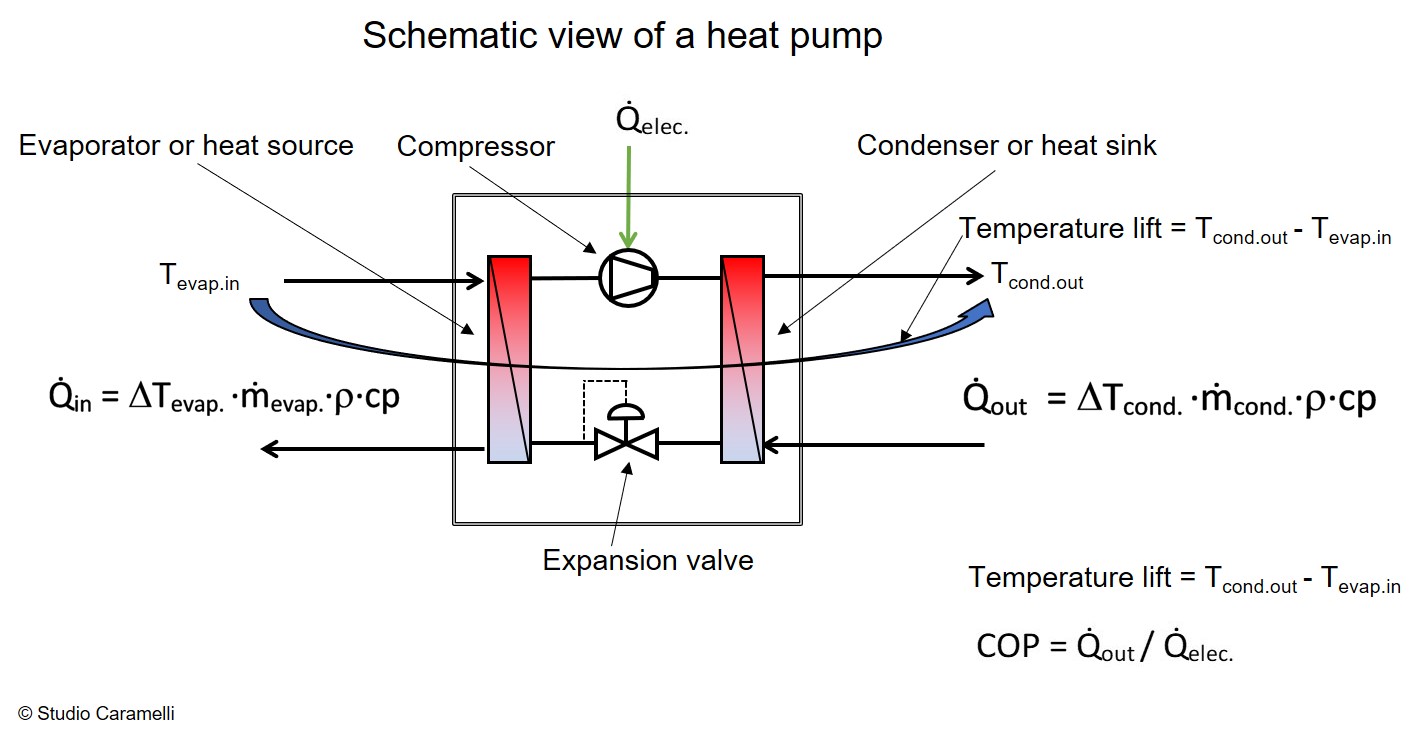
A heat pump is a thermodynamic machine capable of absorbing thermal energy at a certain temperature level and returning it at a higher temperature, using an external energy source. In most cases, the external energy is electricity, but thermal energy can be used as well. The refrigeration machine, invented around 1850, is the most common example of a heat pump. So, the technique is well-proven. Recently, there is a lot of interest in using the same thermodynamic principle to produce heat. The figure on the right shows a schematic representation of a heat pump that uses the mechanical vapor compression cycle. All heat pump cycles use the principle of vapour compression and condensation of a liquid (the refrigerant) in order to obtain the useful thermal effect.
There are many different techniques for vapour compressing and each one has specific characteristics that makes it more or less suitable for a given application (an overview is given here). The electrically driven, closed loop mechanical vapour compression is the most widely used cycle for refrigerators and heat pumps. The figure above shows the principle definitions to describe the energy performance of an electric heat pump.
The COP is a parameter that represents the relationship between the external energy for the operation of the compressor and the thermal energy delivered at the condenser. It is a key indicator because it allows to evaluate the energy savings achieved thanks to the heat pump.
The “delta T” (symbol: ΔT) over the heat pump is defined as the temperature difference between the evaporator inlet flow and the condenser outlet flow temperature (see the figure above).
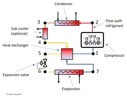
the thermodynamic cycle of the ThermBooster™
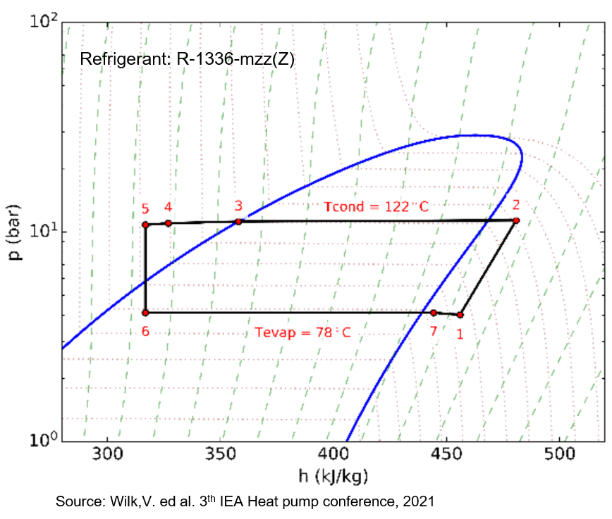
To obtain the temperature increase of the thermal energy, a refrigerant is forced to go through a thermodynamic cycle, with the help of a compressor (see the P-h diagram on the left). The cycle can be broken down into seven distinct processes:
7 → 1: Super heating (with internal exchanger, cold side)
the COP
From the Ph diagram shown above, it can be seen that the useful energy extracted from the machine is represented by the difference between the specific enthalpy of the refrigerant in point 2 and that in point 4, while the work transmitted to the refrigerant by the compressor is represented by the difference between the specific enthalpy of the refrigerant in point 1 and that in point 2.
Therefore:
COP = (h2 – h4) / ((h2 – h1) / ηc)
Where ηc = the isentropic efficiency of the compressor.
For example, a COP = 4 means that in order to produce a thermal flow of 4 kW to the condenser, 1 kW of electricity has to be delivered to the compressor. In this case about 3 kW of thermal energy are absorbed by the evaporator.
It should be noted that the electrical energy absorbed by the compressor is almost entirely returned as thermal energy by the condenser.
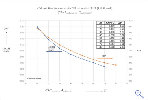
the COP as function of delta T
As can be seen from this graph, the COP decreases when the temperature difference between the evaporator and the condenser increases. From the graph on the left side you can see how the COP changes with a variation of the ΔT (the blue line) as function of ΔT. The graph shows that for small ΔT’s, the changes in the COP are more important than for large ΔT’s. In fact, the variation of the COP with the ΔT goes from 0,18 [1/°C] when ΔT = 10 °C down to 0,03 [1/°C] for ΔT = 80 °C.
N.B. The designer of the plant must pay a lot of attention to this characteristic of the COP, which is typical for all heat pumps and which is critical for the system performance. For example, with a ΔT of 40 °C, the electricity consumption is 43% higher than the consumption with a ΔT of 20 °C.